The Draw Bezier curves and straight lines tool in Inkscape is much like the Pen Tool found in programs like Photoshop. It’s a complex tool that offers a range of potential once you learn how to use it correctly.
You may struggle with the functionality if you have never used the tool or a similar one. Here is a complete guide to help you learn everything you need to know about the tool so that you can draw and edit detailed paths for your artwork and designs.
Table of Contents
What Is the Bezier Tool and How to Access It?
The Draw Bezier curves and straight lines tool, which I will refer to as the Bezier Tool for short, is a pen-like tool that creates custom paths on the canvas. The tool makes paths by adding a node every time you click on the canvas. The areas between nodes are called segments.
The nodes can be added to create straight lines or manipulated to make curved paths. Once you are finished with a path, it will take on the Stroke and Fill that is set. You can then adjust the path’s features, including the stroke and fill color and the stroke style.
You can use paths to create drawings or elements for your layout. These paths are vector objects, so it’s perfect for laser cutting or creating scalable vector objects.
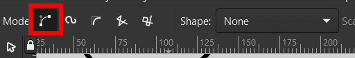
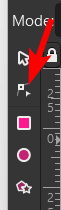
You can access the Bezier Tool by selecting it from the toolbar or pressing B.
How to Draw Straight or Curved Lines Using the Bezier Tool
Once the tool is active, you can start drawing lines on the page to make the path. You can draw straight lines or curved lines using this tool.
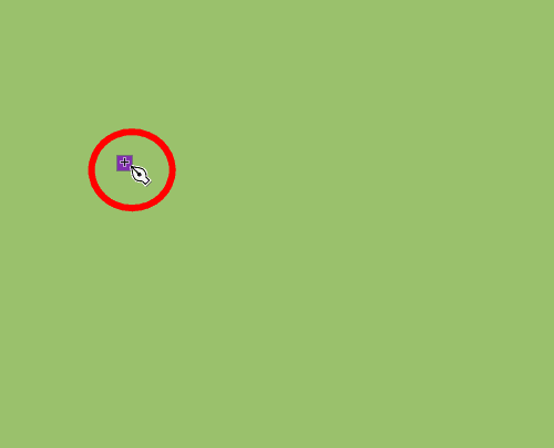
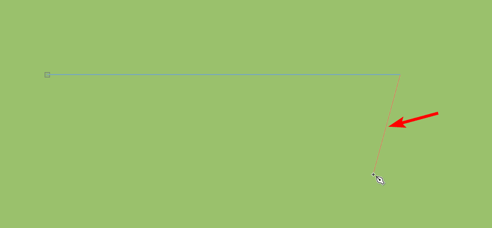
To draw a straight line, click once on the page to add a starting node.
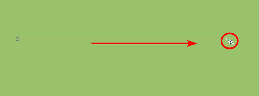
Then, move the mouse across the canvas, and click to add a second node in a straight line. Hold in Control on Windows or Command on Mac before adding the second node if you want a perfectly vertical or horizontal line.
Once you have added the node, when you move the mouse, a new line will appear, letting you continue the path. You can continue adding more straight or curved lines if you want.
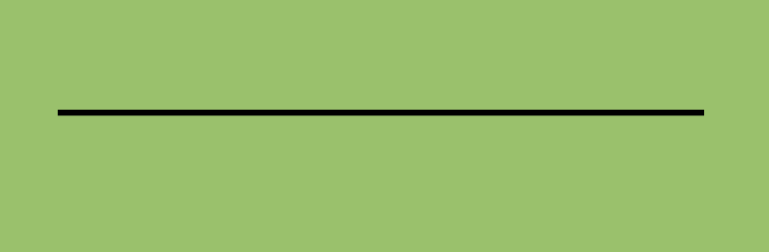
However, if you want to end the path, you can either double-click when adding the last node or add the last node and press Enter.
Once you complete the path, it will take on the current fill and stroke settings.
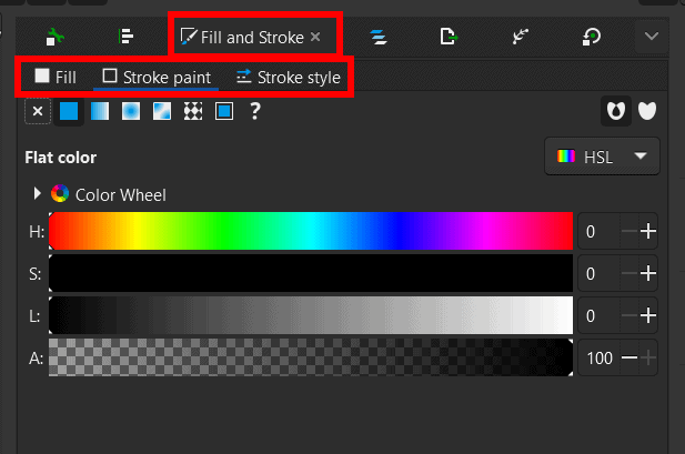
You can edit the stroke and fill settings in the Fill and Stroke panel (Object > Fill and Stroke). The fill doesn’t usually work on open paths, so you should set it to no fill unless you create a closed path.
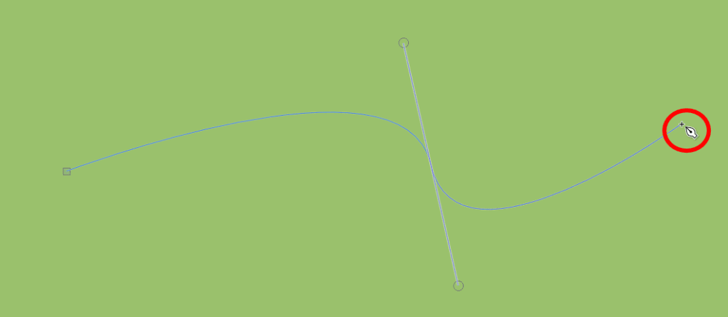
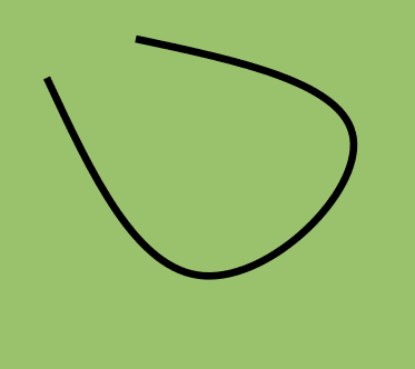
To draw a curved line, click to add the first node. Then, when you click to add the second mode, hold the mouse in or the pen down and drag the cursor up or down to curve the line. If you drag down, the line will curve upward and vice versa.
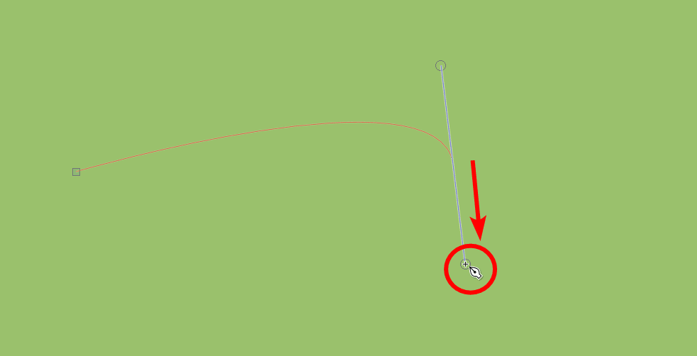
Then, when you move the cursor again, the new line starts from the curve you created. You can then create another curved segment if you want.
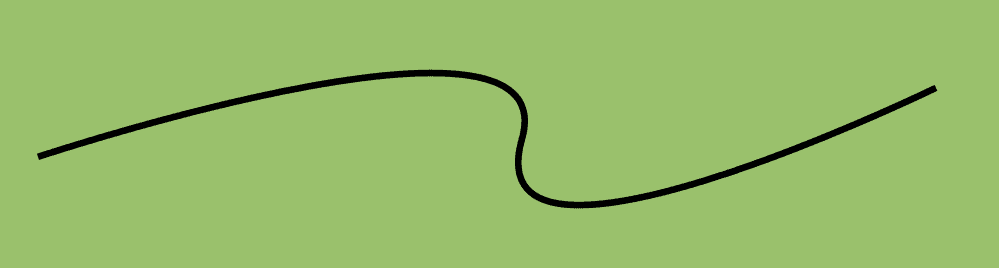
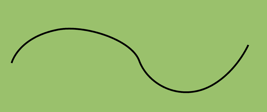
Now, when you complete the path, you will have a curved line.
You can also create a closed path by creating nodes and moving back toward the first node. Once you reach the start of the path, you can click again on the first node to close the path.
Once you close the path, you will have a complete shape.

You can adjust the fill more easily with closed paths.

The 5 Bezier Tool Modes Explained
The above examples were created with the mode set to regular. However, there are four other bezier modes you can use. You can change the tool’s mode in the top settings bar.
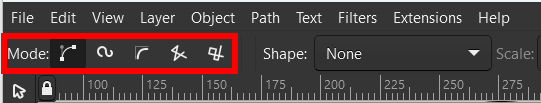
The first method is the Regular mode, which I demonstrated above. This mode lets you create freehand paths.
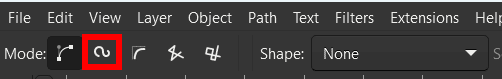
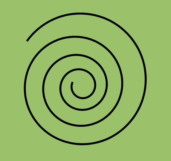
The second icon is the Spiro path mode, which allows you to create smooth rounded curves. You can easily create a spiral using this mode. First, activate the mode by clicking on the icon.
Then, click to add nodes, but you will notice the tool automatically curves the lines.
The third mode is the BSpline path mode, which enables you to create smooth curves that are less rounded than the spiro mode.
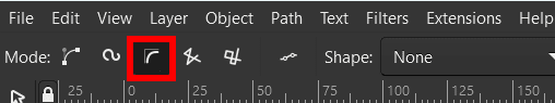
When you add nodes, they curve automatically.
The fourth mode is the sequence of straight-line segments mode, which does as the name implies and creates diagonal, vertical, or horizontal straight lines.
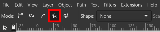
Click to add nodes in a series of straight lines.
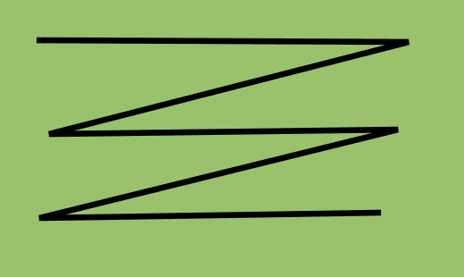
The fifth and last mode is the sequence of paraxial line segments mode, which only allows you to create horizontal or vertical straight lines.
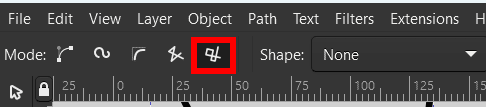
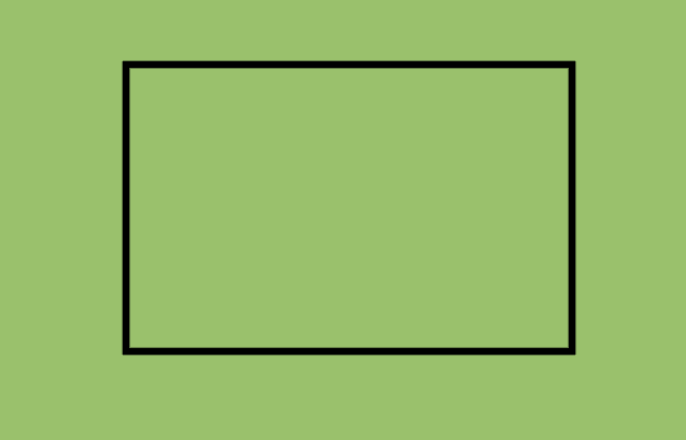
You can click to add nodes and create straight lines, such as to create a rectangle shape.
Bezier Tool Shape Options Explained
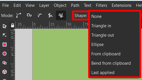
In addition to the various Bezier Tool modes, you can use different shape options with the tool. There are seven shape options to choose from in the top settings bar.
The first option is None, which has been demonstrated in all the examples above as it creates a regular path.
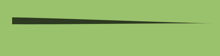
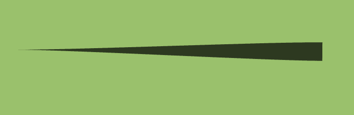
The second option is Triangle In, which creates a triangle shape when you make the path. The path will start thick and taper out at the last node.
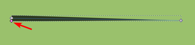
A pink node at the wider end will let you increase or decrease the width.
The third option is Triangle Out, which works the opposite as the previous shape options, creating a tapered end at the start of the path, thickening toward the end node.
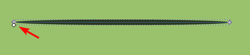
The fourth option is the Ellipse shape, which creates an oval from the first to the end node.
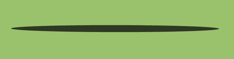
There is a white node that allows you to adjust the width of the oval.
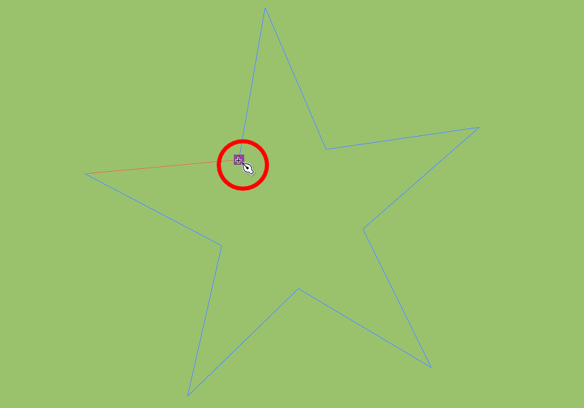
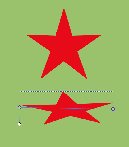
The fifth option is the From clipboard shape, which uses the last object you copied to create the path. For instance, if I copy a red star shape from the canvas when I draw a straight line, it will use the copied shape and color to create the path.
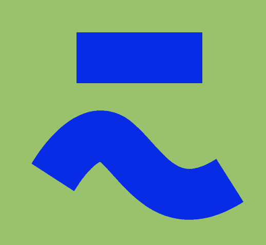
The sixth option is the Bend from clipboard shape, which takes the last copied shape and bends it along the path. For instance, if I copy a rectangle and create a curved path, this is the result.
The seventh option is Last Applied, which uses the last shape setting that was active with the Bezier Tool.
How to Edit Nodes and Handles on the Drawn Path
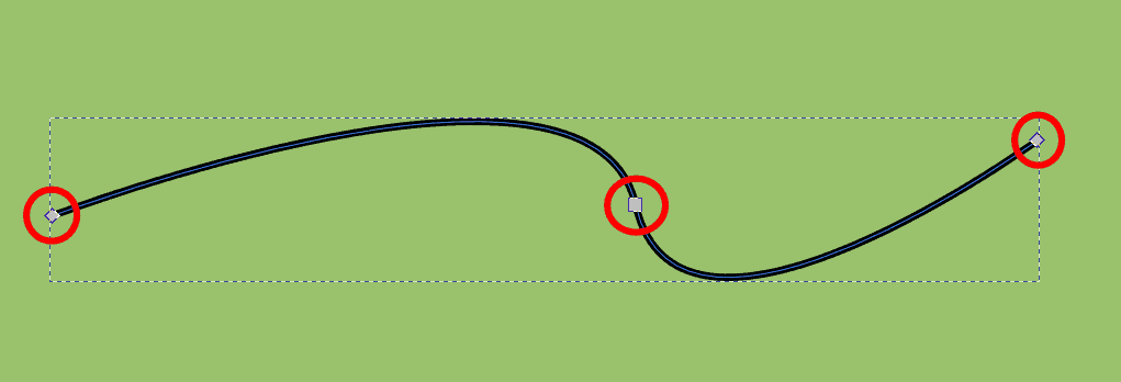
Once you have drawn a path on the canvas using any modes or shape options, you can easily edit the path at any point. To edit the path, activate the Edit paths by nodes tool from the toolbar or press N.
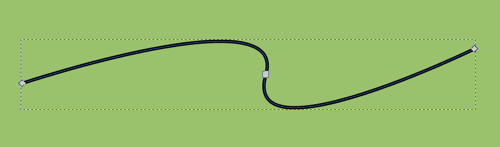
Once the tool is active, you can click on a path to show the nodes, which are small gray blocks.
You can click and drag on a node to move it anywhere.
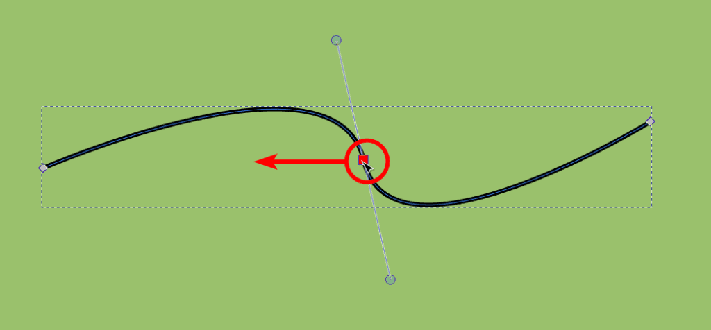
You will notice that when you click on a node, two handles appear on a line attached to the node. You can click and drag on these handles to adjust the path’s curve.
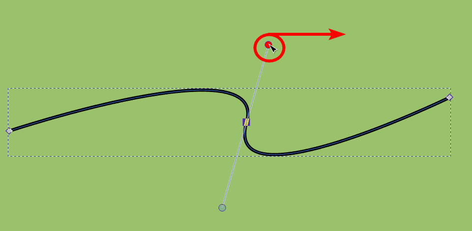
You can move as many nodes and handles as you like to edit the path.
How to Add Nodes to the Path
If you need more nodes to manipulate the path, you can easily add new nodes. Ensure the Edit paths by nodes tool (N) is active and click on the line to show the nodes.
Then, double-click anywhere on the path to add a node. You can add as many nodes as you need.
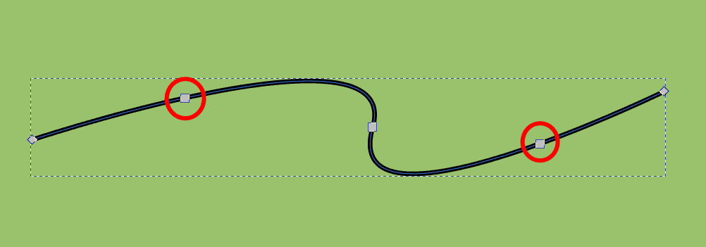
Now, you can adjust the new nodes to manipulate the path further.
👍 Support Us: Subscribe to our channel and help us continue providing these tutorials.
🌟 Regular Updates: We publish how-to videos for Inkscape regularly!
🔧 Expert Guidance: Learn Inkscape from our professionals and uncover exclusive tips!